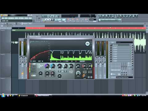

The signal flow chart does little to explain how to use Maximus so we have provided some tutorials to help you understand the diverse capabilities afforded by Maximus. Operator's ears where it is met with large nods of approval. Finally, the signal is sent to the plugin outputs and onto the The same processes used on the frequency sub-bands (as described above) may be applied. Once processed, the signal is then recombined and (optionally) down-sampled (General Options), as it passes to the final MASTER compression stage. Saturation (SAT THRES, SAT CEIL, Band Process Controls).If the compression stage has lowered the final output level, thisĬan be used to restore the overall band volume. Post compression gain or 'Make-up gain' (POST GAIN, Band Process Controls).Compression curve (Compression Envelopes).May be used to boost the input signal into the active range of the compression envelope. Pre compression gain (PRE GAIN, Band Process Controls).Enhances or reduces the stereo content of the signal. Stereo Separation (, Band Process Controls).

The LOW/MID and MID/HIGH boundaries are user-variable, according to the LOW and HIGH controls (LOW FREQ, HIGH FREQ, Band Frequency Controls) as are theīand-split filter types (IIR or Linear-phase, General Options ). Up-sampled (General Options, lower Analysis Display), to improve the quality of the next stage - band-split filtering, The input signal may be Lo cut (LO.CUT, Band Frequency Controls) to remove subsonic energy, improving headroom for the remaining 'audible' frequencies. If you want to learn how to use Maximus, this is the place to start. This page has two sections, the first section explains signal routing possibilities in Maximus while the second section delivers a series of tutorials spanning the basics through to some of the


 0 kommentar(er)
